Monday, March 21, 2016

Post-Project Report

The last time we talked, I only had 9 hours and 36 minutes completed for my Senior Project. That was three months ago, and now I've finished all of the needed hours (which was 30). It's been a long and semi-confusing process, but we finally have a working system and have been modifying it to be more efficient. A lot has happened since December 8, 2015, so let's go over what's changed.

For all you know, I could still be in the middle of drafting the machine itself, but I have the finished system sitting in a box on my shelf right now. What happened immediately after the last post is the construction and completion of the circuit box and the physical system, as well as creating and completing a working circuit.


After drafting the different designs, we went with the "spike" one (you can see the drafts in the last post). We measured and cut the spike from some aluminum and made it large enough to fit the circuit box, then we drilled holes through both the spike and the box so they could attach to each other. After that, we placed some rubber stoppers between the plate and the circuit box so we could place the wiring through the holes and have some wiggle room.


Below are three profiled photos of the design we went with:

1.) The Spike lying on its side. The point closest to us is where it sticks into the ground.

2.) This shot is at the same angle as before, but the heat sink is holding the Spike up.

3.) This captures the shape of the Spike. It's more of a wedge, really. This is what it would look like from the front once it was placed in the ground.

After attaching the box to the Spike, we worked on our circuit. The first image is of our original circuit, before we made it smaller. We drew this one and cut pieces out or shortened everything. We went through seven versions of drafts before we were able to make the circuit as tidy and tiny as possible. The second photo is the breadboard lying inside the circuit box after we screwed it in. The one after that is our final circuit, laid out inside the box.


Our thermistor ready for being attached to the circuit.

The peltier cooler and its collection rods, also ready to be attached.

After the circuitry was in place, Mr. Kennemore lent me his multimeter and I placed the Spike in my front yard, where the solar panel would be able to get as much sunlight as possible during the day, then the system would run at night. I attached the multimeter in series with the Spike system so I could just turn it on to get an amperage reading.

The mound of plastic has the multimeter wrapped in it as a safeguard against water. It's also holding the open connections between the multimeter, solar panel and Spike to keep them from shorting.


I set the Spike outside for five days (Monday through Friday night) and collected readings from the multimeter each night. At first, the collection rods were full of water, but as the week wore on there was noticeably less. Friday's rods had very little water. A common theme throughout the week, though, was that none of the water ever made it into the cup below. We figured that the water couldn't break its own surface tension and was evaporating while it clung to the rods.


Early week rods.

Friday night's rods.

Mr. Kennemore offered some ideas for modifying the Spike, which I added the next day. One was to tip the Spike by placing it in the ground on an angle. The other was to add a small piece if metal just under the rods, so that any water hanging down would touch the metal and break its surface tension. Then the tilt in the Spike would allow the water to run down the metal and into the cup below.


However, these modifications still didn't yield the expected result. The entire time the Spike was out, it was only drawing 30 mA on average, when the number was supposed to be around 600 mA. We replaced the batteries in the solar panel with fully charged ones and put it out again, letting the system run through one day and one night. When I checked, there was a substantial amount of water there, and some even made it down into the cup. Most of it was busy making its way down the metal and into the cup. The only problem was that the multimeter still read 40 mA. Obviously there are still some bugs, but the system worked the way we wanted it to.


Tuesday, December 8, 2015

Project Update #1

Alright. So far a lot has been accomplished. Here's a list that I'll go in-depth with in a second: we took apart a solar panel (one of those one's people have in their backyard for garden lanterns), we took the solar panel and used it to test our circuit, we tested our thermo-electric cooler's water collecting capabilities, chose our heat sink, tried different cooler possibilities, and came up with our final design(s) for the overall system.

Before I jump into talking about all those things, I'd like to discuss our thought process on the whole subject of "self-regulating water condenser". What we are trying to do is create a system that waters plants on its own. To do this, we are incorporating solar panels, Peltier coolers (which were covered in the previous post), light sensors, etc. And all of these get to be put on a circuit together.

Currently, my experience with circuiting amounts to the most basic of ideas. I've only really ever used resistors, LED's, jumper wires, and power sources. The circuit for this specific system involves more advanced things like transistors (with their PNP or NPN setups) and capacitors, along with the previously mentioned items.
 
http://goo.gl/ITpCEB

Needless to say, it's easy for me to get lost.

So large chunks of my research have been spent looking into the smaller parts of our project, so I can understand what these instruments do. If you're interested, here's a link to some information about capacitors, and one about transistors. The internet has been very helpful in my search to comprehend the reasons why we're using this apparatus. For instance, did you know that RC (resistor-capacitor) Circuits are composed of resistors and capacitors and can effectively make a timed current? Easy-to-understand facts like this are the reason I haven't been completely lost, and there's a plethora of information to be learned.

Let's move on to what Mr. Kennemore and I have completed.


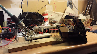
Above is an image of the opened solar panel next to a soldering iron. We had taken it apart to have easier access to the panel's inner-workings. We wanted access to the panel's wires so we could test the panel in our circuit.


After I soldered our wires to the panel's original wires, we used something called "heat shrink". The heat shrink in this case are those grey, rubber tubes hanging off of the red and grey wires in the above picture. We moved the heat shrink of the soldered wire junctions and heated up. Heat shrink shrinks when heated up, so it sealed the junctions. This makes for a smoother wire after soldering, which is always better than wires with frays and bumps.


In this image, we've connected the solar panel into the circuit we made to see if it worked. Mr. Kennemore is holding his thumb over the panel's light sensor. It's hard to see in the picture, but there's a small, red LED towards the right end of breadboard. This LED is lit in the picture, because when the light sensor stops sensing light, it stops storing energy and starts pumping it through our circuit. This is what we wanted. We are trying to make it so that when the solar panel senses that it is nighttime, it will stop collecting energy and send its current through the circuit to our thermo-electric cooler.


The top image of the copper cylinders is a closeup of our thermo-electric cooler (which is actually the small white square the copper is sitting on. The copper is coated in water because we ran current through the circuitry in the square. Manipulating the cooler has been extremely easy. We've been able to effortlessly condense water on it. The only problem is that sometimes we set the wires backwards, which heats up the cooler, but that's easy to fix. The bottom picture is a picture of me putting thermal adhesives on the bottom of a second set of copper cylinders. This one was sprayed with water-proofing, which we were hoping would allow the water to have an easier time dripping.

I want to mention that I messed up a few of the adhesives. They are very temperamental and only like the cleanest of surfaces, or else they will get ruined. Also, if you touch the bottom of the adhesive, it has a high chance of not working. I had to try a few times to delicately peel the plastic off and set the adhesives to the cylinders.


This is our heat sink. Since Peltier coolers have sides that cool and sides that heat up, we needed a heat sink for the side that heats up. This heat sink takes the heat from the cooler and disperses it over a larger surface area, so it cools off faster, thus reducing the chance of our system overheating. This heat sink is huge compared to our cooler, so it doesn't get very hot, whereas our cooler can get very cold.


Last time Mr. Kennemore and I met, we agreed on two final designs. It has been hard mentally visualizing what the final product will be, so he wanted me to draft them. This picture shows me drawing the idea I came up with, where we could drill a metal bracket onto our heat sink, support our circuit box above that, and hang our cooler over a plant as the bracket hangs the entire thing on the edge of a pot. Closeup images are below.


Mr. Kennemore's original design involved conjoining the circuit box to the back of a spike, which could be stuck into the dirt of a potted plant to allow the cooler to drip water onto the plant. In both designs, the circuit box has wiring that leads to the solar panel, which can be placed in places for maximum sunlight during the day.


When we next meet we will focus on building the frame for our cooler. I've also been thinking about other designs that we can try and use that may be more efficient than the two we have already. We'll only be focusing on the general body of our product because we want to see how much room we have to cram our circuit in to (because it depends on the size of our circuit box). We ran into an issue with our circuit. Mr. Kennemore thinks that the transistors we have aren't working the way they should be, so we'll work on fixing our circuit separately from building the body.

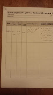
So that's all for now. Below our images of my Form B with my signed of hours. If you can't read it very well, it comes out to 576 minutes, or 9 hours and 36 minutes.


Monday, November 9, 2015

A Self-Regulating Water Condensor


The point of my Senior Project is to construct a self-regulating water condenser. My mentor, Charles Kennemore, works at Viavi Solutions. Instead of going to Viavi Solutions to work with optic-based technology, Mr. Kennemore told me about a project he wanted to try: using a water condenser to water plants without any human intervention.


https://goo.gl/xnrUog


The idea is based off of the Peltier effect, named after Jean Charles Athanase Peltier. The Peltier effect occurs when an electric current is passed through two semiconductors. If the conductors are made of dissimilar materials and currents are passed through the free ends, heat moves from one end to the other. The heat wants to go from high energy states to low energy states, so the heat moves across the conductor system.

http://goo.gl/VxBoR2

In the above picture, "P" and "N" are referring to p-type and n-type semiconductors.

The Peltier effect can be used to manipulate the temperatures on either side of the Peltier cooler. The more current running through the cooler, the higher the temperature change that can be achieved. With this in mind, if we use a Peltier cooler at night, we could drop the temperature of the cooler to the dew point. The dew point is the temperature at which dew forms by condensing from the air. The dew point drops as the temperature drops, but stays roughly the same. By changing the temperature of the cooler to below the dew point, water will condense onto the cold side of the cooler.

So far, we've figured out that the most humid time of day is from 11 P.M. to 7 A.M. In that timeframe, the dew point is 19 degrees under the average temperature. Using graphs we found online, we determined that we would need at around 1.5 Amperes of current to get a 19 degree change. The amount of Volts we need may be large to draw that amount of current for such a long time, though.

 http://goo.gl/3NXp0y


The plan for this Peltier cooler is to start with a solar cell and a light sensor. During the day, the solar cell will charge the batteries. When the light sensor stops sensing the presence of light, it will open the circuit and not allow any more current to travel from the solar cell to the batteries. Then, at around 11 P.M., a timer will close its switch and complete the circuit, allowing current to flow from the batteries into the free ends of the cooler.


I have been instructed to look into several topics for this system. For instance, we need a way to disperse the heat from the hot side of the cooler. We could use a heat sink - a conductor with a moving coolant fluid inside that cools the material - or we could use a teethed-effect (as seen in the picture below) to maximize surface area and get rid of heat.


To be able to make the circuit self-regulating, we may need to employ thermistors. Resistors control the amount of current that pass through them. Thermistors do the same thing, but resist more current when they are at a lower temperature. With this in mind, we could have a heat sensor checking on the thermistor, and if it gets to a certain temperature and is letting too much current through, the heat sensor could open a switch to stop the circuit.

http://goo.gl/I3A4cO

An assortment of different thermistors.

I have also been looking into the best metals to use, which shapes have the most efficient volume-to-surface-area ratio, what kind of batteries we should use, and black-body radiation, among other things.

Next, we will work on testing circuits and constructing parts of the circuit itself. Mr. Kennemore mentioned testing which batteries work best and figuring out how much they will drain if we run 1.5 Amperes for eight hours. Before we actually start building the cooler and the circuit, we need to figure out how much room we will need, where we would want to put it, what we can do to minimize cost and materials, and how we can get the light sensor to work with the solar cell.