Before I jump into talking about all those things, I'd like to discuss our thought process on the whole subject of "self-regulating water condenser". What we are trying to do is create a system that waters plants on its own. To do this, we are incorporating solar panels, Peltier coolers (which were covered in the previous post), light sensors, etc. And all of these get to be put on a circuit together.
Currently, my experience with circuiting amounts to the most basic of ideas. I've only really ever used resistors, LED's, jumper wires, and power sources. The circuit for this specific system involves more advanced things like transistors (with their PNP or NPN setups) and capacitors, along with the previously mentioned items.
http://goo.gl/ITpCEB
So large chunks of my research have been spent looking into the smaller parts of our project, so I can understand what these instruments do. If you're interested, here's a link to some information about capacitors, and one about transistors. The internet has been very helpful in my search to comprehend the reasons why we're using this apparatus. For instance, did you know that RC (resistor-capacitor) Circuits are composed of resistors and capacitors and can effectively make a timed current? Easy-to-understand facts like this are the reason I haven't been completely lost, and there's a plethora of information to be learned.
Let's move on to what Mr. Kennemore and I have completed.
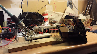
Above is an image of the opened solar panel next to a soldering iron. We had taken it apart to have easier access to the panel's inner-workings. We wanted access to the panel's wires so we could test the panel in our circuit.
After I soldered our wires to the panel's original wires, we used something called "heat shrink". The heat shrink in this case are those grey, rubber tubes hanging off of the red and grey wires in the above picture. We moved the heat shrink of the soldered wire junctions and heated up. Heat shrink shrinks when heated up, so it sealed the junctions. This makes for a smoother wire after soldering, which is always better than wires with frays and bumps.
I want to mention that I messed up a few of the adhesives. They are very temperamental and only like the cleanest of surfaces, or else they will get ruined. Also, if you touch the bottom of the adhesive, it has a high chance of not working. I had to try a few times to delicately peel the plastic off and set the adhesives to the cylinders.
Last time Mr. Kennemore and I met, we agreed on two final designs. It has been hard mentally visualizing what the final product will be, so he wanted me to draft them. This picture shows me drawing the idea I came up with, where we could drill a metal bracket onto our heat sink, support our circuit box above that, and hang our cooler over a plant as the bracket hangs the entire thing on the edge of a pot. Closeup images are below.
Mr. Kennemore's original design involved conjoining the circuit box to the back of a spike, which could be stuck into the dirt of a potted plant to allow the cooler to drip water onto the plant. In both designs, the circuit box has wiring that leads to the solar panel, which can be placed in places for maximum sunlight during the day.
When we next meet we will focus on building the frame for our cooler. I've also been thinking about other designs that we can try and use that may be more efficient than the two we have already. We'll only be focusing on the general body of our product because we want to see how much room we have to cram our circuit in to (because it depends on the size of our circuit box). We ran into an issue with our circuit. Mr. Kennemore thinks that the transistors we have aren't working the way they should be, so we'll work on fixing our circuit separately from building the body.
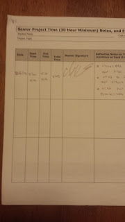
So that's all for now. Below our images of my Form B with my signed of hours. If you can't read it very well, it comes out to 576 minutes, or 9 hours and 36 minutes.


